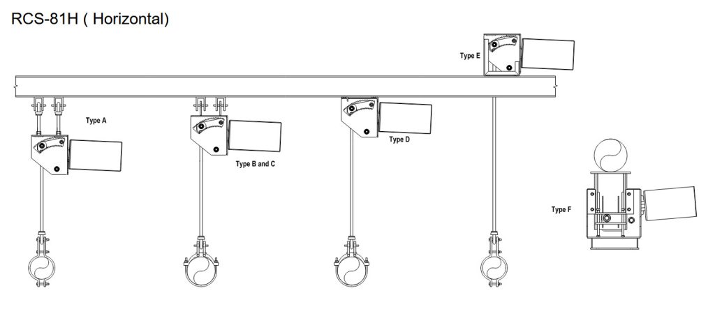

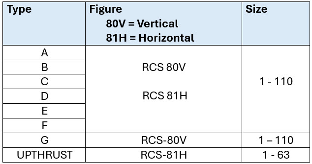
A Type
B Type
C Type
D Type
E Type
F Type (UPTHRUST)
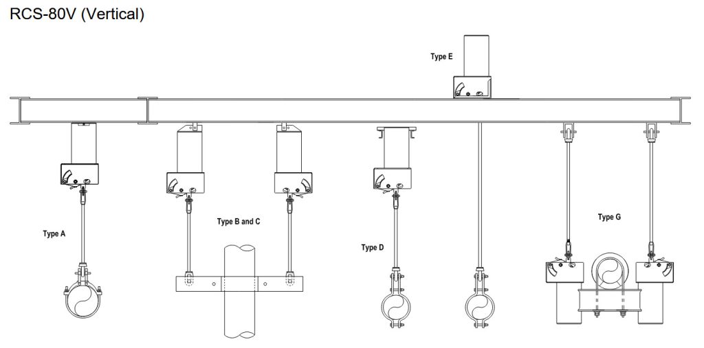
A Type
B Type
C Type
D Type
E Type
G Type