Variable Spring Supports

Variable springs are used to support piping which is subject to thermal expansion and other factors which cause the pipe support point to move. They are called “Variable” because the force exerted by the “spring” varies through their range of travel. As the supported pipe moves upward, the force exerted by the “spring” decreases. Conversely, during downward travel, the force of the “spring” increases.

Recommended Service

Generally used to support piping where thermal movements cause the system position and dimensions to change. Also commonly used where the transfer of an uncontrolled load can cause damage to the equipment. A “Variable” spring may not necessarily be recommended in all the above applications, however. As an example, when the variability surpasses 25%, a “Constant” support should be used.

Specifications

All of the RILCO spring units are designed to meet or exceed the requirements of the ASME Code for Pressure Piping, ASME B31.1, B31.3, and MSS SP-58.

Design Features - Standard
  • Load indicators are visible in the travel slots and the loading is easy to read.
  • All springs are protected from weather conditions and damage by the spring casing.
  • Closure plate operates as a centering unit and a guide sustaining spring alignment.
  • Every size has reserve travel (over travel) at both higher and lower boundaries of the operating range of the spring.
  • Springs are calibrated for accurate loading.
  • Spring and casing are fabricated from steel making them compact and rugged.
  • Cold set at the factory to exacting customer requirements.
  • The spring coil is epoxy powder-coated to provide protection to the coil, while the unit is hot-dipped galvanized per ASTM A153 protecting the unit from corrosive and climatic conditions.
Design Features - Optional
  • “Limit stops” installed in order to accurately limit spring movement.
  • Lifting lugs-available on all sizes.
  • Optional casing and component finishes.
  • Available fabricated entirely from stainless steel, including coil.
  • Adjustable Travel Stops available upon request on spring sizes 15 and larger.
Figure, Type and Size

RILCO Variable Short Spring Hanger, the RVS-82, has all of the features of our RVS-268 and is designed to same exacting specifications.

The RVS-82 is best utilized in confined areas where thermal movement of the piping is relatively small. The RVS-82 hanger is offered in seven basic types which are displayed on this an the following page.

The Variable Selection Chart for sizing and instructions are on the 4th tab above.

Use the chart below for dimensions of type A, B, C & D
Use the chart below for dimensions of type F & G. For Type E, email us info@rilco.com

The RILCO RVS-268 is the spring upon which all the other RILCO RVS spring designs are based.

The compact design enables this spring to work in a wide range of applications. The interchangeability of parts between spring figures also allows these units to be the most cost effective means of providing support to piping systems and other vertical displacement applications. The RVS-268 provides a recommended maximum of 2-1/2″ of movement, with a wide range of load carrying capability. On applications which require only a minimal amount of movement or are spaced restricted, the RVS-82 springs might better suit the designers’ needs. Refer to the RVS-98, triple, or quadruple for instances which call for increased travel.

The Variable Selection Chart for sizing and instructions are on the 4th tab above.

Use the chart below for dimensions of type A, B, C & D
Use the chart below for dimensions of type F & G. For Type E, email us info@rilco.com

RILCO Variable Double Spring Hanger, the RVS-98, has all of the features of the RVS-268 features and is designed to the same exacting specifications.

Each unit consists of two springs arranged in series within a single casing and a centering guide to assure the permanent alignment of the spring assembly. The RVS-98 hanger is offered in seven basic types as shown on this and the following page.

The Variable Selection Chart for sizing and instructions are on the 4th tab above.

Use the chart below for dimensions of type A, B, C & D
Use the chart below for dimensions of type F & G. For Type E, email us info@rilco.com

RILCO “Variable Triple Spring Hanger” has all of the features of our RSV-268 and is designed to the same exacting specifications.

Each basic unit consists of three springs arranged in series within a single casing and a centering guide to assure the permanent alignment of the spring assembly. This hanger is offered in the seven basic types shown on this and the following page.

The Variable Selection Chart for sizing and instructions are on the 4th tab above.

Use the chart below for dimensions of type A, B, C, D, F & G
Use the chart below for dimensions of type F & G. For Type E, email us info@rilco.com

RILCO “Variable Quadruple Spring Hanger” has all of the RVS-268 features of our RVS-268 and is designed to the same exacting specifications.

Each basic unit consists of four springs arranged in series within a single casing and a centering guide to assure the permanent alignment of the spring assembly. This hanger is offered in the seven basic types as shown on this and the following page.

The Variable Selection Chart for sizing and instructions are on the 4th tab above.

Use the chart below for dimensions of type A, B, C, D, F & G
Use the chart below for dimensions of type F & G. For Type E, email us info@rilco.com

The type of “Variable Spring” hanger to be utilized depends upon several variables. Those include the physical characteristics of the hanger attachment, whether it will be supported above or below the spring and the potential of interference from other components. The “Variable Spring” hangers illustrated above, Types “A” through “G” represent the seven standard types available. They are described as follows:

Type B

The unit has a single lug for attachment to the structure to permit connection with a bolt or pin to a clevis or welded beam attachment. For use where headroom is limited.

Type C

The unit has two lugs welded to the top of the casing to permit connection with a bolt or pin through a single lug attachment on the structure. Also designed for limited headroom applications.

Type D

Designed for use where the variable spring is positioned above the supporting structure and the spring adjustment is made from the top.

Type E

Also designed for use where the variable spring is positioned above the supporting structure, but the spring adjustment must be made from below the structure on which the case is supported.

Type A

Unit is attached to the supporting member by a vertical rod threaded into the top of the case.

Type F

Designed to support piping from below. Used to support pipe from the floor or where support from overhead is not practical.

Type G

For use where headroom is limited or an obstruction prohibits the use of a single rod type Variable Spring.

Load Selection Procedure - (English Unit)

Variability is the key principle in selecting the figure and size of a variable spring support. Variability is determined by calculating the change in percentage of the supporting force of a variable spring between the hot (operating) and cold (installed) loads using the following formula:

Variability = (Movement x Spring rate) /Hot (operating) load

If the variability is in question, a lower variability is more desirable. The lower variability does not transfer as much stress to the adjacent equipment at the cold (installed) position than a spring with higher variability. To comply with requirements of MSS SP- 58 specifications, variability should not exceed 25%. If the design conditions cause the variability to exceed the recommended maximum, RILCO strongly suggests the use of one of our Constant Supports instead of a variable.

Spring Hanger Figure and Size Selection

Case 1: Only one of the loads is known – either operating (hot) load or installed (cold) load is known

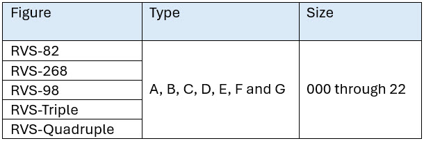
1.  Select a spring figure (RVS-82, 268, etc.) with a working range which will accommodate the travel.

2. Find a spring size where the load is approximately in the middle of the working range loads.

3. Calculate the missing load (either Hot or   Cold) by using the following formulas:

     Hot (operating) load = Cold (installed) load – (Travel x Spring rate) or Cold (installed) load = Hot (operating) load + (Travel x Spring rate)

4. Verify that both loads are within the working range, preferably equidistance from the center of the load chart. Variable Springs.

5. If the loads are at either extreme, select a new spring size and re-calculate the missing load until both the loads are satisfactory.

6. Calculate the variability, which should not exceed 25%.

Case 2:  Both operating (Hot) load and installed (Cold) loads are known:

1. Select a spring size where both loads are ideally equidistance from the center of the load chart.
2. Calculate the movement with the following formula:

Movement = [Cold (installed) load – Hot (operating) load Spring rate

3. Select a Spring figure (RVS-82, 268 etc.) which will give a variability lower than 25%.